Optimizing Requirement Management in Business Analysis: SYTOSS's Experience
How to keep the information contained in a major Software System under control? How to achieve the maximum possible coverage with requirements at each stage of a software development project, or multiple projects, in a complex corporate environment?
In the article, we would like to share with you the result of our Requirement Management research our BA department conducted a while ago and the resulting reorganization of the roles and responsibilities within a Software Project. Our work is based on our more than 15 year-long experience in managing and documenting the software projects we have been implementing for our Telco clients. As a result of the above reorganization, our software projects have received highly positive feedback from Sytoss's clients with regard to the quality of the software and its timely delivery.
The Theory: The Way It All Should Be
The Requirement Management process is key for any project's success. Proper requirement management allows one to eliminate scope creeps, project cost overruns, and delays. Controlling scope creeps and the quality of the requirements is essential. The early identification of the requirements-related issues allows avoiding design problems that are difficult and expensive to fix (especially, when the development is already underway) and may result in the project being delivered belatedly or over budget. On the other hand, requirements often contain features that are never used by the end user. Thus, investing in the implementation of a more optimal requirement management approach always has a great positive effect, even if this is done at a later stage when the project is already well into implementation.
Prior to opting for a Requirement Management Approach, it is important to have an understanding of the goals you are going to achieve by taking this approach. First of all, the requirements must be accurate and well-organized. They must be organized in such a way that they are understandable to all the stakeholders, including any kind of an SME, Analyst, Manager, Tester, and Developer. A requirement must be as exhaustive as possible, and the risk of having "unknown" requirements must be reduced as much as possible. The requirements must provide requirement traceability, so that it is always clear where the information they contain originates from and who is its source.
Next, we need to analyze what the Requirement Management process is and what are its constituent stages. Any project starts with the Requirement Planning stage. During this stage, a Requirement Management Plan is developed, reviewed, and approved. The next stage is Gathering and Elicitation, during which we try to collect as many requirements as possible. The Requirement Definition stage follows this stage. Here, we organize, define, refine, and document the requirements and then have them approved by the stakeholders.
Next comes the Requirement Analysis stage, during which we collect any existing unknown requirements and turn them into known ones. The Requirement Verification stage is intended to answer the question of how the requirements are covered in the development plans, quality assurance tests, and verifications.
The last stage we will consider important for purposes of the process changes, described herein, is the Requirements Change Management one. At this stage, we follow the procedure, defined during the Requirement Management Planning stage.
The OLD Way
Initially, we had the following process established in our company. Conventional old documents in an electronic form were used to store the requirements.
There were two types of documents used: those that stipulated "how it should be" and those that defined "what needs to be changed":
a DFS, or Detailed Functional Specification. The document contains the initial requirements as received by us at the start of a project. The document defines "how it should be". The project was divided into several development areas, such as Backend, Frontend, Interfaces, and others. Basically, each development area was linked to a specific development team, so, in essence, each of the areas had its own DFS covering it.
CR or Change Request. The document specifies changes to the base DFS document and belongs to the "what needs to be changed" type. The document reflects those changes that were agreed upon with the customer after the requirements contained in the DFS had been implemented. A single CR document, normally, contained changes that had occurred in multiple development areas, each being described in a separate section of the document. After the implementation of the changes contained in the CR, we performed the "consolidation" procedure, intended to merge the changes in the main DFS document and, thus, keep the "how it should be" project specification up-to-date.
Both the document types contained the Functional Specification and the Technical Solution to be implemented, i.e., the software modules to be modified were mentioned. The database objects were specified together with log messages, error codes, and some other low-level technical information. The external and internal integration were mixed inside the documents. The documents were authored by Business and System Analysts. In case any low-level Technical Detail issue occurred (such as, for example, the wrong translation to another language, or an incorrectly specified DB field), a System Analyst had to be tasked with this issue's resolution.
Below you will find a detailed description of how the main stages of the Requirement Management process had been organized before overhauling it.
The Process of Requirements' Gathering, Definition, and Analysis
As at the Requirement Gathering stage the Customer completed a Fact Sheet document, there was a definition of how the system was supposed to work from the business perspective, or as part of an integrated solution involving some other software systems, used by the company or its partners.
During the Requirement Definition stage, a Business Analyst uses the Fact Sheet to prepare the Functional Specification. This information is then passed on to System Analysts, and, here the Requirement Analysis stage began. The System Analysts collected all required information and proposed several solution options. This included the software systems to be implemented from scratch or modified, any existing restrictions, and a rough estimate of the development effort. The documents were approved by the customer and released for development.
The Documentation Storage and Versioning
There was a centralized storage for the documents that could be accessed by the customer, BAs, and the development team. The storage was organized as a network file share. There is a predefined hierarchy divided by Development Area and document type. Each change or feature had its own folder that could contain several documents associated with it. The changes that migrated from one version to another were tracked using the Track Changes feature of Microsoft Word. This allowed seeing the changes that had been made since the previous version of the document.
Requirement Change Management
Any new change was introduced by creating a Change Request ticket in the Task Tracking system. The description provided a definition of the core requirement. Based on the ticket, the DFS or CR was modified, and a new version was created. The Document was approved and implemented in accordance with the established release process. The release process involved verifying whether there were any contradictions between the Document's different versions (which is a frequent happening when multiple contributors work on the same document). Next, the document was placed in the shared folder, and the team members involved were notified that there was a new version of the document available. Hereon, the Requirements document was regarded as valid, and the development process could be commenced.
Problems with the Old Requirement Management
We found that the existing requirement management system and organization of the project roles and responsibilities was encumbered with the following disadvantages:
The change tracking was a complex and manual process. Moreover, it took a great effort to understand what exactly had been changed, for example, between software releases. The change consolidation process took up time, and it often looked like you had to do the same things twice. In addition, in accordance with this approach, several team members had to be working on the same document, and this often resulted in version collisions or some information being lost.
The task of locating some information was a challenge: information contained in electronic documents could not be indexed and referenced well. There was no complete catalog of this information available in any form. Basically, you just had to know where to look for a specific piece of information, and it could well take up an entire day to find something you needed.
Generally, testers and developers were not business-centric, or, even, self-thinking enough to try to understand the purpose of some functionality. Most of them tended to just look at a document, do exactly what it is said, and seldom saw the logic and dependencies behind the text. This resulted in project delays due to integration failures.
System Analysts focus on Software Architecture, Requirements, and Technical Solutions. They would get overloaded with petty tasks, mostly bug-fixing ones, as well as minor issues that could be resolved by the developers. It became impossible to allocate them to any new project.
The New Way
We decided to improve our Requirement Management Process. As the process was, also, closely intertwined with the different roles and responsibilities, the improvement effort entailed a reorganization of the team's working process as a whole.
The Goals of the Process Improvement Effort
As the first step, clearly define the goals that the reorganization was aimed to achieve:
Making the requirements' organization User Role-centric.
Making the search for any requirement much simpler and easy even for newcomers.
Automating the document versioning and some other procedures as much as possible.
Proving the ability to easily reference information.
Providing easy and secure access to the document storage from anywhere.
Seamlessly integrating the document storage with the Task-Tracking system.
The Design
We started by analyzing the requirements structure and divided the broad range of information to be stored by class, category, and other criteria. We tried to make the new classification as detailed as possible. When the classification was ready, we defined a strict hierarchy for its different parts, indicating the way those parts were linked together and the rules, in accordance with which each of the parts was organized. We decided that the atomic pieces of information be separated on the information pages (repository, glossary, etc.) to be referenced from everywhere. Each page was to be referenced so that we could easily access this page later.
The User Roles and Their Needs
The basic needs that had to be provided for in accordance with the corresponding roles were as follows:
Business Analyst or Domain Expert: The information required by a Business Analyst is a high-level view of the system from a business perspective. Thus, they, basically, needed to see business process definitions and information on any existing integrations with external systems. Therefore, to support the Business Analysis purposes, we split the contents into Business Use-Cases and the Interfaces Repository.
System Analyst: Some Business Cases involve multiple software systems. To provide a proper solution, a System Analyst requires a high-level integration view of the systems involved and the information exchange between them. To cover this, we introduced Integration Use-Cases.
The Integration Use Cases are structured as a table, where each Business Case or some part thereof is a row, while the software systems are columns. Each of the systems has a brief description, indicating the system's purpose and its connection with a specific Business Case. In addition, there is a link to a corresponding System Use-Case, which contains detailed processing info related to this system.
It is also expedient to have a Repository where logical entities are defined with their attributes. The Interface Repository we have created helps us locate information on the existing integrations with external systems.
Software Developer: The Software Developer is responsible for the Technical Solution, Database Objects, Files, Logs, and so on. The Software Developer's contribution is associated with a System Use-Case, defining how the system must work, the Repository, containing the logical Data Model and the Interfaces Repository, defining the rules for the information exchange with external systems.
As a result, the Software Developer is responsible for maintaining Technical Design, pages. These pages contain the implementation details that can prove helpful in problem investigations and the fulfillment of other low-level technical tasks.
Quality Assurance Engineer: This Role uses the System Use-Case and Integration Use-Case as inputs for building a test strategy. Business Use-Cases help understand Customer needs. The QA Engineers are responsible for maintaining Test Cases pages.
Project Manager: Implementing each new feature involves defining the changes that need to be made. This definition must have the "what needs to be changed" form, rather than the "how it should be" one, used by all the above roles. This helps understand the impact made by each change and estimate the required effort. For this reason, we introduced a special category called "Projects".
Information Page Categories
Based on the above User Roles, we defined the following Information Page Categories to be supported:
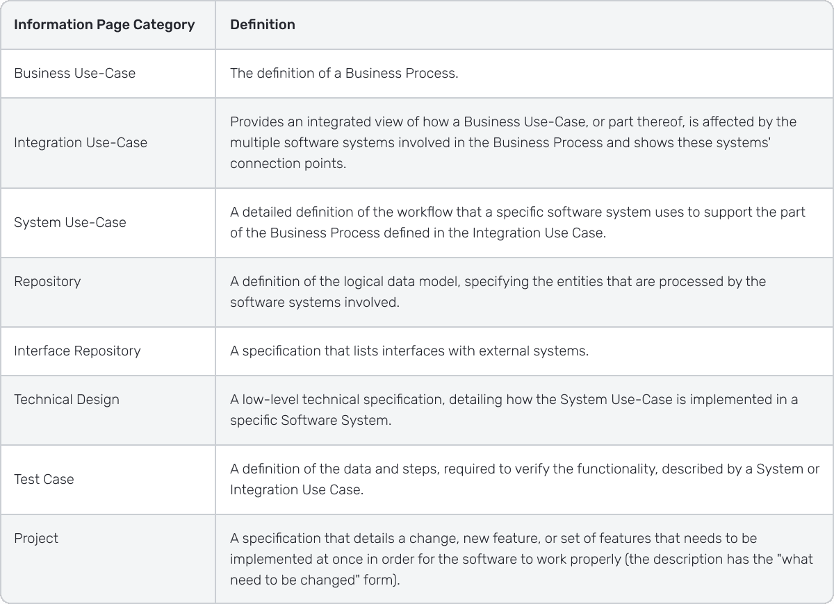
Example
Assuming there is an Internet Provider Lucky Bit, which specializes in the Residential market. They want to automate their Business Process. Having conversed with their Domain Expert, a Business Analyst has defined the following Business Case:
Business Use-Case #B1: "New Customer Is Connected"
Prerequisite: The new customer wants to connect their apartment to the Internet.
Actions:
- 1. The Customer visits the company's Front Office and communicates with a Customer Service Representative (CSR).
- 2. The CSR checks the connection possibility and offers one or more active Internet products.
- 3. The Customer selects the Internet Product and supplies its Contract and Location information.
- 4. The CSR offers to sign a contract, and the Customer signs it.
- 5. The CSR creates a connection installation ticket for the Technicians department.
- 6. The Technicians Department contacts the Customer and agrees on the installation date.
- 7. Technicians visit the Customer's location and perform the installation on the designated date. When the task is complete, the Technician closes the ticket. This activates the Internet Connection and related Billing.
Result:
The Customer has Internet access in accordance with their selected Product package. The Billing process for the connection is activated.
The above Business Use-Case is transferred to a System Analyst. Their work starts with System Architecture Design. A real-world project contains many Business Use-Cases. The software systems required to support the Business Use-cases, are selected by the System Analyst through the analysis of the available Resources and Technologies. Multiple systems can be required:
1. Customer Care system — manages Customers and their products.
2. Provisioning system — manages connections on the network hardware level (network elements, switches), connects, and disconnects the Customers.
3. Billing System — calculates the Customer Product's cost and generates an invoice.
Several Integration Use-Cases cover the above Business Case:
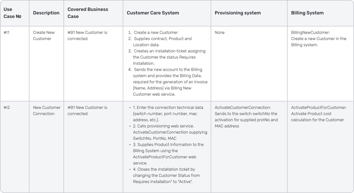
As we can see from the above cases, it is now clear which Software Systems are involved in the Business Use-Case and in which way. Now, it's time to define what exactly each Software System must do and introduce a System Use-Case for this purpose.
For the #I1, Customer Care system, the Use-Case will look as follows:
System Use-Case #1: The CSR receives an order to create a New Customer
Prerequisite:
1. The Customer fills in the contract form, signs it, and hands it over to the CSR.
System/User Action:
- 1. The CSR opens the CustomerCare application on the main screen and clicks the New Customer button.
- 2. The CustomerCare opens the New Customer dialog box. The dialog boxes requires that the following data needs to be entered ( see also <Link to="" the="" Customer="" business="" Object="" in="" the="" repository=""> for data types and validations ):
- 1. Contract Information:
- 1. Customer Name: Mandatory
- 2. Customer Address: Mandatory
- 2. Authentication Information:
- 1. UserName: Mandatory
- 2. Initial Password: Automatically Generated
- 1. Contract Information:
- 3. Product Information:
- 1. Product Package: Select from the list of active packages to the moment. Mandatory.
- 2. The CSR enters the data and press Add button.
- 3. The CustomerCare creates the Customer Business Object in the local database with all the entered information. Set the Customer status to "Requires Installation".
- 4. The CustomerCare sends the new Customer Business Object to the Billing system, providing the Billing Data required for the Invoice ( Name, Address) via the BillingNewAccount web service.
- 5. The above operations are logged.
- 6. CustomerCare opens the Customer Business Object Information screen (see UC # xxx for details).
Expected:
- 1. The Customer is available in the CustomerCare system with the status "Requires Installation", and all its attributes are visible on the Customer Information screen (see UC # xxx for details).
- 2. The Customer Object is available in the Billing System with the specified Name and Address.
Error Cases:
- 1. Some mandatory attribute is missing: It's impossible to continue with the Add button.
- 2. Error Creating Customer locally:
- 1. The CSR sees a meaningful error message.
- 2. The Customer is not created locally in the DB.
- 3. The Web Service is not called, the account is not created in the Billing system.
- 4. The error is logged.
- 3. Error Creating Customer in Billing System:
- 1. The CSR sees a meaningful error message.
- 2. The Customer is not available locally in the DB.
- 3. The Customer is not available in the Billing system.
- 4. The error is logged.
The Repository
The Repository includes one page that defines the Customer Business Object and its attributes:
Customer Business Object — Repository
| Name | Type | Mandatory | Description |
|---|---|---|---|
| Customer Name | String, 256 characters | yes | The Customer Name as specified in the Contract. |
| Customer Address | String, 256 characters | yes | The Customer Address as specified in the Contract (also used as the installation address). |
| Username | String, 40 characters | yes | The login name for the accounting system |
| Password | String, 40 characters | yes | The password. Must contain upper and lower case characters, special symbols, and digits. Minimal length — 8 characters. |
| Product ID | Reference | no | The product reference to one of the products offered by the company |
| Account Status | Enumeration | yes | One of the following:
|
Technical Design
The contents of the Technical Design page are specific to the tools and frameworks used in the project. Thus, instead of a real-world example, we will provide below what can be expected to appear on the Technical Design page:
- 1. The Database type, The Data Model, Technical ERD
- 2. The modules and frameworks used to implement the System Use-Case and their configuration.
- 3. The processing workflow that is based on the Data Model and includes some specific logic, required to be implemented on the frameworks. In short, the source the data must be obtained from must be indicated (a reference to the Data Model), as well as how this data must be → transformed and stored.
- 4. The exact contents of the GUI information messages, their translation, and meaning.
- 5. Logging-related information: message types, exact texts and error codes, the log message description, and Operations actions.
Test Case
The Test Case is written based on an Integration or System Use-Case. A single Use-Case is normally covered by several Test Cases where different sets of inputs are applied, and the expected result is specified for each of those.
Structuring the Information
Cross-Linking
As you can see, we implemented grouping by Information Page Category based on the needs of the main project roles.
Next, it was necessary to structure the created set of categories in such a way that it would make it easy to navigate across any related information. We analyzed the more common search patterns and introduced a documentation storage structure that fit them best.
Below, you will find several definitions of our newly introduced documentation storage structure.
From the Business perspective:
- Business Use-Case -> Integration Use-Case -> System Use-Case -> Repository
- Business Use-Case -> Repository
- The Repository can be browsed using a page tree.
From the Project Management perspective:
- Project -> Business Use-Case
- Project -> Integration Use-Case -> System Use-Case ->Technical design -> Test Case
From the Business/System Analysis Perspective:
- Business Use-Case -> Integration Use-Case -> System Use-Case -> Repository -> Technical Design
- Project -> Integration Use-Case -> System Use-Case ->Technical design
- The Repository can be browsed using a page tree.
From the Software Developer Perspective:
- System Use-Case -> Repository -> Technical Design
From QA Perspective:
- Business Use-Case -> Integration Use-Case -> System Use-Case -> Repository -> Test Case
Based on the above search patterns, we performed the cross-linking of the pages in such a way that it has become easy to determine which of the top-level pages relates to a lower-level page and vice versa, for example, which System Use-Cases are associated with a specific Business Use-Case and where one can find the Technical Design that covers a specific System Use-Case.
It is now easy to see the reason for implementing the feature, defined in a Technical Design or the Business Use-Case, for which this feature needs to be implemented. It is also easy to identify the Business Use-Cases that are affected when the implemented feature does not work as expected.
Thus, with a properly organized cross-linking of the pages in place, we have achieved the best traceability possible. The cross-linking of the page categories is shown on the diagram below. In addition to the linked pages, you can also see the User Roles that maintain and use these pages more frequently.
Grouping as a Single Page Tree
In addition to the cross-linking, the User often needs to see the full list of features implemented, so there was the need to introduce another structure dimension: the pages are now organized as a tree. On the top level, they are grouped by the Information Page Category. Each category has its own grouping schema for the pages within the top-level group.
- The Business Use-Cases are grouped by business area.
- The Projects is a flat list with numbers that define the chronology.
- The Integration Use-Cases, System Use-Cases, and Repository are grouped by the Business area.
- The Technical Design is grouped by software modules and subsystems.
- The Test Cases follow the Integration and System Use-Cases' structure.
Managing Changes and Versioning
We cross-linked the page tree using a well-defined organization. It became much easier to track the dependencies between different documents.
Now, we were faced with the task of implementing the change management process in a way that would allow us to preserve the introduced organization, track any changes made, compare the different versions of documents and keep a changelog.
One's approach to this task hinges upon the capabilities of the software platform we select for the storage of requirements. It is also important that the page and their versions management platform are integrated with the task-tracking system used by the company.
Requirement Change Management
During the early stage, one can initiate a change by opening a new Project. It is where the Business Analysis phase commences.
The Project page is filled in during the Requirement Gathering and Definition stages. This stage results in the creation of new Business Use-Cases, or updating of the existing ones.
Next comes the System Analysis stage, during which the bulk of the Requirement Analysis is performed. It becomes possible to evaluate the impact made by a change on the existing system and make approximate development effort estimations.
As a result, new Integration and System Use-Cases and Repository pages are created, or some of the existing ones are modified. The Task-Tracking tickets, required for Development, must be created prior to the beginning of this stage. Upon completion of this stage, a list of the Integration and System Use-Cases is sent to the Development Team.
During the Development stage, a Technical Design is prepared or modified. Simultaneously, Test Cases are prepared by the QA team.
All the pages (excluding the Projects page) always stay in the "how it should be" state so that it is clear how the system has been working up till now. Any change triggers the creation of a new version of a page. The new version contains a mandatory ChangeLog entry field, in which the one or more Task-tracking tickets are specified. Any user who has made some changes starts being tracked automatically.
The Benefits of the New Way
What are the main differences between the new model from the old one and its main advantages over the latter?
All the related information is now cross-linked. It is easy to locate a set of pages related to a topic in other categories by just following the provided links.
A page contains less information as compared with the old-style documents. Each page is built on a set of rules, which makes the pages compact. It, in turn, renders perception, versioning, making concurrent changes, and tracking changes a great deal easier.
The page management takes less time due to the versioning process being automated. The Information structure makes task-tracking and referencing a lot easier.
Due to the Requirement Change Management workflow having been modified, the roles and responsibilities have been reorganized as well. The Development has become more business-centric, and the System Analysis Role is no longer overloaded with bug-fixing. Consequently, they have more time to take part in other projects.
All the above allows us to keep the Requirements under control at all times. The newly introduced system has already proven to be a lot more efficient on several occasions and helped us make these projects a success.
Tools
Finally, let's dwell on the practical implementation of the Requirement Management Approach.
There are lots of tools available these days that can be used to implement the approach under review. We opted for the Atlassian JIRA ad as the Task-Tracking system and Atlassian Confluence as a storage for the Requirement Pages.
This choice has the following benefits and restrictions:
The Benefits
JIRA and Confluence are products developed by the same company, and they are tightly integrated.
You can see a set of JIRA tasks associated with the Information Page, while on a JIRA task, you see a set of the linked pages, so basically it's very easy to see the implementation status of a Requirement, its change history and where the information originates from. Thus, combining the two applications ensures great requirement traceability.
The Confluence application is capable of keeping a history of changes. Its Information Page allows conveniently comparing different versions. Changelogs are generated automatically. The software includes a good change notification system.
The Restrictions
The Confluence application is designed to show you the latest valid information and has no mechanism that allows cross-linking the previous versions of pages. Thus, discovering the "how it was before" state of a requirement has to be performed manually.